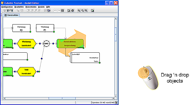
You can drag objects, which are in the presentation panel with the mouse and drop them at any position. Please note that some objects cannot be moved (e.g. lines which are connected on both ends). Furthermore you cannot move objects if you only have the reading rights for the presentation, but you are not allowed to modify them.
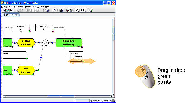
You can change the size of objects by holding the green points with the mouse and moving them. The move can be restricted both vertically and horizontally. Available modification to individual objects depend on the modeling language you are using. If you want to modify something, please contact your responsible method engineer.
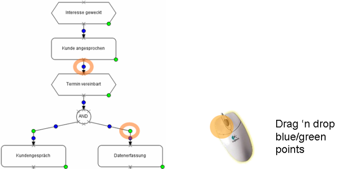
In Cubetto Toolset, lines can possess an unlimited number of bends, i.e. sections. If you want to add a bend to a line click a blue point and drag it a bit away from the line. If you then release the point, the line will be divided into two connected sections. You can change the position of the bend, when changing the size of an object, by dragging the green point at the bend.
Segments snap in if the connected segments are horizontal or vertical, thus substantially easing the moving of connected segments. Should the snap-in process not be wanted, press the Control key (Command-key or Apple key on Mac-Os) while moving a bend.
If you want to delete a bend, move the bend between the two adjacent points. If the green point does not disappear on its own, click once on it.
Please note that not all lines are able to have bends. The possibilities depend once again on the modeling language in use. If you want to modify something, please contact your responsible method engineer.
Related help topics:
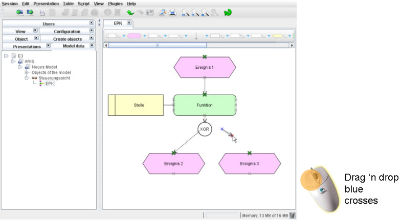
You can connect objects by shifting the blue crosses (connectors) on top of each other. You can use grey crosses only as destinations, but they cannot be moved.
Hold a connector with the mouse. Possible destination connectors are highlighted in green. Drag the connector on top of one of the highlighted connectors to establish the connection. Red highlighted connectors mean: The modeling language in use does not allow a connection at this point.
IMPORTANT NOTE: Hold the Control key (Command-key or Apple key on Mac-Os) when loosing the connector to create a connection with the next object. This reduces the mouse precision required.
If and how many objects can be connected depends on the modeling language in use. If you have questions, please contact your responsible method engineer.
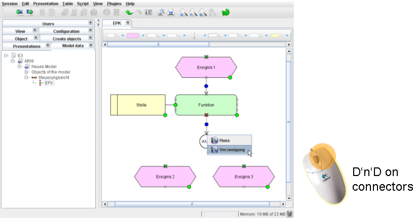
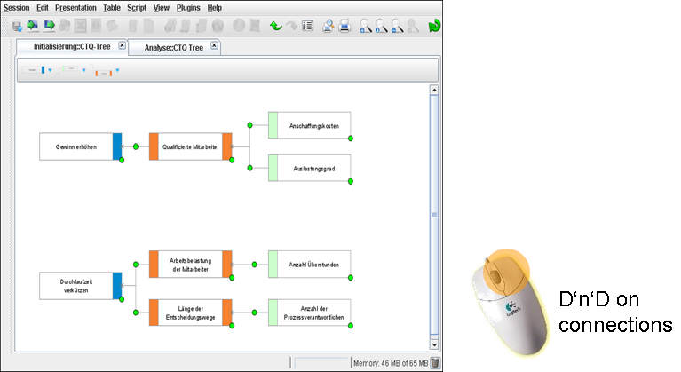
Connections can also be established by Drag-and-Drop two existing connectors. In this way it is also very easy to create new "neighbour-objects".
To disconnect objects, right click on the connector and select the command Disconnect. As a result all connectors at the selected position are deleted.
To ease the object disconnection, select the connector with the mouse and drag it away from the object. If you want to disconnect two movable connectors you need to press the Control-Key simultaneously.
Related help topics:
Before creating an object in the presentation panel, you should decide first, if you want to create a new object or want to paste an object, which exists in another presentation or view already.
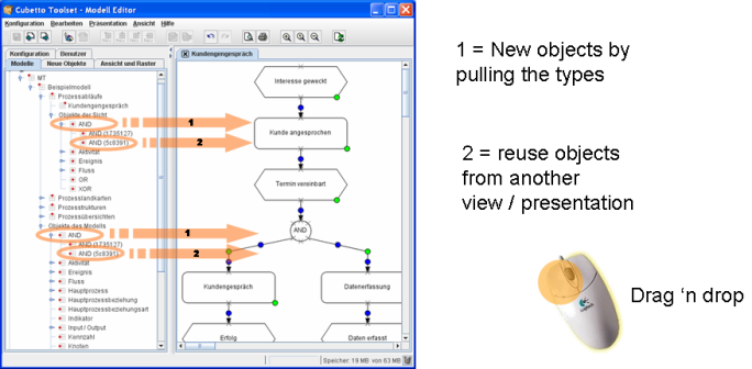
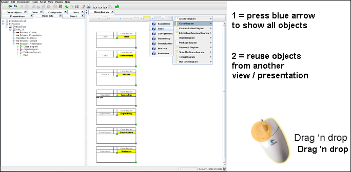
To create a new object, the best thing to do is to open the tab New Object in the Model Editor or display the bar for new object at the upper end of the presentation panel. Afterwards drag the graphic you want into the presentation panel. By holding the Control key (Command-key or Apple key on Mac-Os) the new object will automatically be connected to adjacent ones.
It has the same effect, if you open the tab Model and drag an Object Type into the Presentation Panel. The new object is from the selected type and appears ,straight after dropping it, in the tree below the Object Type itself.
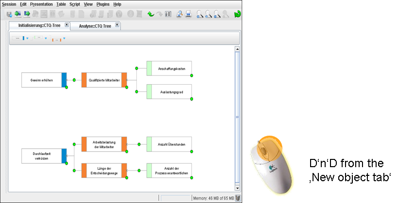
If you do not want to create a new object, but want to paste an object, which already exists in another presentation or view into the Presentation Panel, you drag the respective object from the tree into the Presentation Panel.
It has the same effect, if you click the blue arrow beside the graphic in the new object tab. All existing objects will be shown in a pull down menu.
Related help topics:
To edit objects in the Model Editor, double click the relevant graphic. The Object Editor, which opens up, is an easy way to edit the properties of the selected object. Another way to edit objects is the tab Object. Therefore, just select the object and open the tab.
Related help topics:
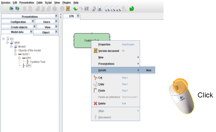
Some modeling languages allow to connect objects to other presentations. E.g. a process step can be refined in second presentation. Such presentation connection can be easily created using the context menu of the relevant object. You can find continuative help at Edit Model Refinements
Related help topics:
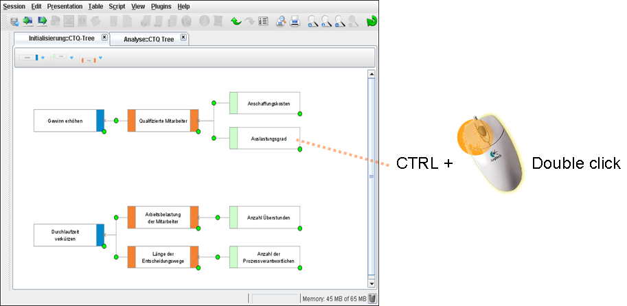
Some modeling languages allow to connect objects to other presentations. E.g. a process step can be refined in second presentation. Such presentation can be opened by clicking the object and simultaneous holding the Control key (Command-key or Apple key on Mac-Os).
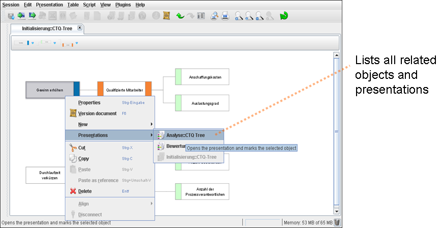
Reciprocally, you can display objects connected to the currently opened presentation by right-clicking the presentation panel and selecting the menu item from the context menu. A list of all objects connected to the current presentation as well as all presentations containing those objects will be displayed.
Related help topics:
Sometimes you might want to align objects in the Presentation Panel on one line. This can have a positive effect on the legibility and therefore on the quality of your models.
In the Cubetto Toolset you proceed for this as follows:
Mark all objects in the Presentation Panel, whose position you want to align.
Select the alignment function you want from the menu.
The elements will be aligned to the object, which is the furthest away, i.e. when aligning to the left, you align to the object, which is the furthest on the left. The following alignments are currently possible:
 Top
TopAligns the objects to the top most element.
 Bottom
Aligns the objects to the bottom most element.
 Left
LeftAll marked objects are aligned to the left.
 Right
RightAll marked objects are aligned to the right.
 Vertically
centered
Vertically
centeredThe elements are aligned on a vertical line.
 Horizontally centered
The elements are aligned on a horizontal line.