The graphic editor is used to create and edit graphics. Graphics are necessary to describe the concepts of a modeling language and consist of individual elements that can be connected to each other by their components and their coordinates.
The graphic editor user interface comprises three parts. The left hand side features tabs containing suitable graphics elements and tabs allowing to control the display. The middle part shows the graphics to be processed, and the part on the right hand side features context tabs containing functions and characteristics of a selected element.
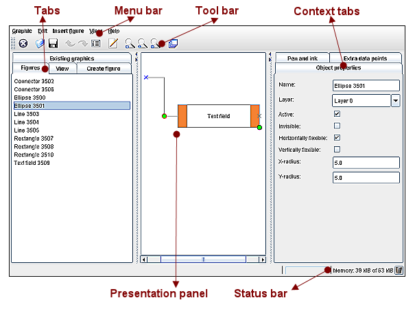
- Menu bar
The menu bar and its items give access to all functions available in the graphic editor.
- Toolbar
Contains symbols corresponding to the main commands and provides a quick access to frequent used functions.
- Tabs
The left hand side contains for example tabs displaying the figures used and allowing the setting of the presentation panel parameters.
- Context tabs
The context tabs on the right hand side contain the functions and characteristics of the selected element.
- Presentation panel
The presentation panel enables to edit the current graphics.
- Status bar
The status bar provides information about the application storage capacity requirements and the current processing status.